
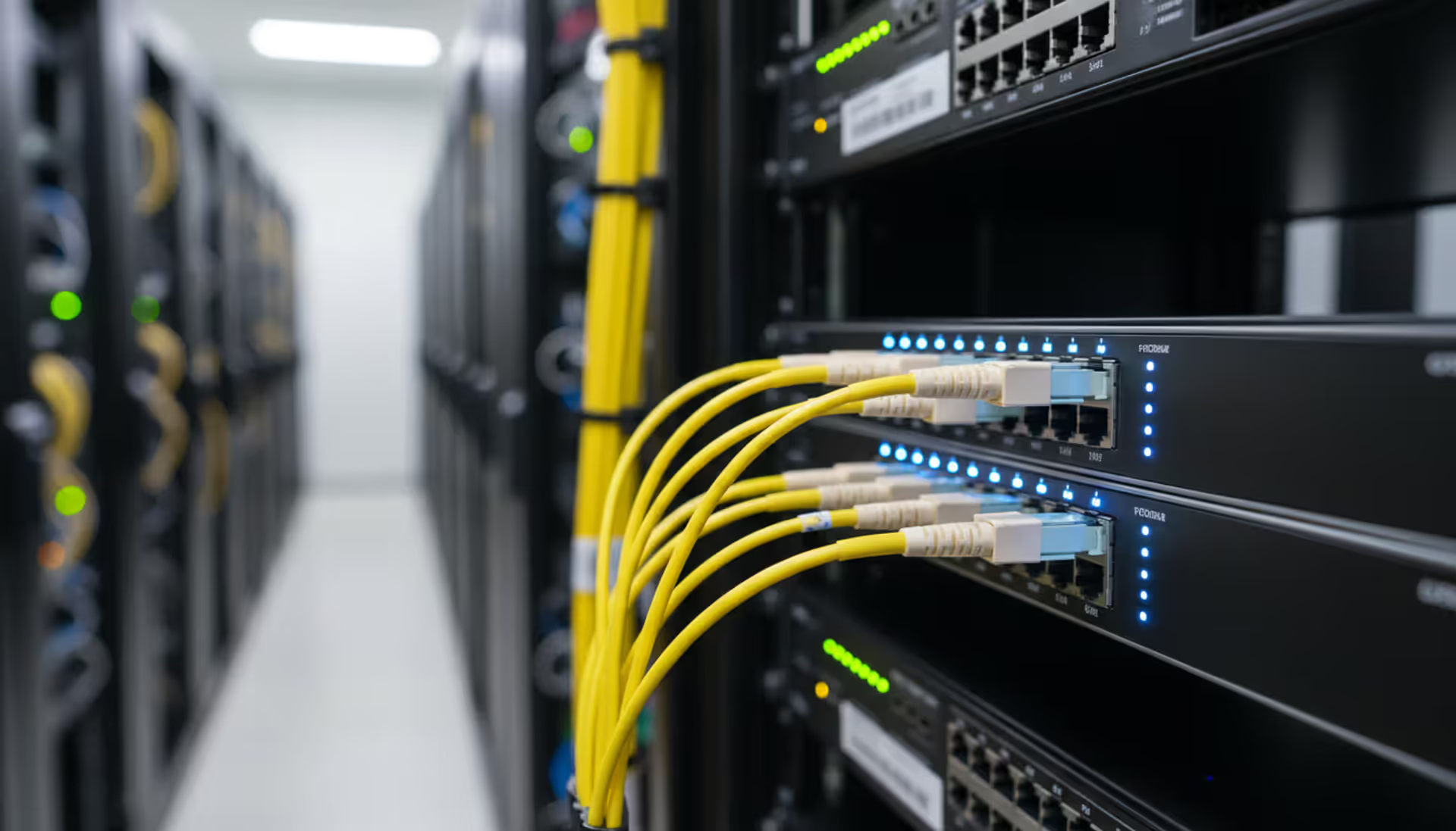
Yellow single mode fiber optic cables with LC connectors plugged into a network switch in a modern data center rack with blue LED indicators
Single Mode Fiber Guide

Content
Content
Single mode fiber remains the backbone of long-distance telecommunications and high-bandwidth enterprise networks. With hyperscale data centers pushing transmission distances beyond 100 kilometers and 400G/800G deployments becoming standard, understanding the nuances of single mode fiber specifications, connector types, and deployment scenarios directly impacts network reliability and total cost of ownership.
What Is Single Mode Fiber and How Does It Work
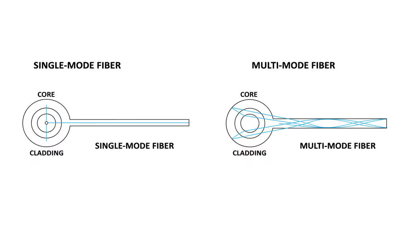
Single mode fiber uses a narrow glass core to transmit light signals along a single pathway, or mode. Unlike multimode fiber where light bounces at various angles through a wider core, single mode fiber's tight core diameter forces light to travel in essentially one straight line. This fundamental difference eliminates modal dispersion—the signal degradation that occurs when different light paths arrive at slightly different times.
The physics behind this approach centers on the relationship between core diameter and wavelength. When the core diameter approaches the wavelength of the transmitted light (typically 1310nm or 1550nm), the fiber supports only the fundamental propagation mode. This creates a clean signal that can travel extraordinary distances without regeneration.
Transmission capabilities separate single mode fiber from other options dramatically. While multimode fiber typically maxes out at 550 meters for 10G applications, single mode fiber routinely handles 40 kilometers at 10G and can extend to 120 kilometers with the right optics. Bandwidth capacity scales similarly—single mode fiber supports 100G, 400G, and emerging 800G standards across metropolitan and regional distances where multimode would require prohibitively expensive signal boosting.
The core size specification directly influences these performance characteristics. A smaller core reduces the chance of higher-order modes propagating, but requires more precise alignment during splicing and connector termination. Manufacturing tolerances measured in fractions of a micron determine whether a cable meets specifications for long-haul deployments.
Author: Caleb Merrick;
Source: clatsopcountygensoc.com
Single Mode Fiber Core Size and Technical Specifications
The 9/125 micron standard defines single mode fiber construction worldwide. The first number—9 microns—represents the core diameter where light actually travels. The second number—125 microns—specifies the outer diameter of the glass cladding that surrounds the core. For perspective, a human hair measures roughly 75 microns in diameter, making the single mode fiber core approximately one-eighth that width.
Cladding serves a critical function beyond structural support. The refractive index difference between core and cladding creates total internal reflection, keeping light confined within the core. Standard cladding uses pure silica glass with a refractive index around 1.444, while the core contains silica doped with germanium to raise its refractive index slightly to approximately 1.447. This 0.003 difference seems trivial but proves essential for light confinement.
The 125-micron cladding diameter wasn't arbitrary—it matches multimode fiber cladding dimensions, allowing the same connector ferrules, alignment sleeves, and termination equipment to work across both fiber types. This standardization reduced manufacturing costs and simplified field deployment when single mode fiber gained widespread adoption in the 1990s.
Wavelength compatibility determines which optical transceivers work with your fiber installation. The 1310nm wavelength offers lower dispersion, making it ideal for high-speed data transmission up to 10 kilometers without dispersion compensation. The 1550nm wavelength experiences lower attenuation (signal loss), extending reach to 40 kilometers or beyond. Many modern deployments use coarse wavelength division multiplexing (CWDM) or dense wavelength division multiplexing (DWDM) to transmit multiple signals simultaneously across different wavelengths on the same fiber strand.
Mode field diameter (MFD) provides another specification worth understanding. While the physical core measures 9 microns, the electromagnetic field extends slightly into the cladding. At 1310nm, typical MFD measures 9.2 microns; at 1550nm, it increases to approximately 10.4 microns. Mismatched MFD between connected fibers causes insertion loss—a common issue when splicing older G.652 fiber to newer bend-optimized G.657 fiber.
Understanding Single Mode OS2 Standard
OS2 classification represents the performance tier for single mode fiber rather than a physical cable type. Defined in ISO/IEC 11801, OS2 specifies maximum attenuation of 0.4 dB/km at 1310nm and 0.3 dB/km at 1550nm. These tight tolerances ensure signals maintain integrity over extended distances, making OS2 suitable for both indoor and outdoor applications.
Author: Caleb Merrick;
Source: clatsopcountygensoc.com
The OS1 vs OS2 distinction causes confusion because both use identical 9/125 micron fiber. The difference lies in cable construction and rated performance. OS1 typically refers to tight-buffered indoor cables with maximum attenuation of 1.0 dB/km at 1310nm and 1.0 dB/km at 1550nm—adequate for campus backbones but insufficient for metropolitan networks. OS2 encompasses both indoor tight-buffered and outdoor loose-tube designs, but with stricter attenuation requirements that enable longer spans.
In practice, most fiber manufactured since 2020 meets or exceeds OS2 specifications regardless of cable construction. The designation helps specifiers ensure their chosen cable supports planned transmission distances. A 15-kilometer span with 0.5 dB connector loss at each end requires fiber with maximum 0.4 dB/km attenuation to stay within typical transceiver power budgets—OS2 provides that headroom while OS1 might not.
Distance ratings for OS2 fiber depend on the optical transceiver and data rate. At 10G using 10GBASE-LR optics, OS2 fiber supports 10 kilometers. Upgrading to 10GBASE-ER extends reach to 40 kilometers. For 100G applications, 100GBASE-LR4 transceivers achieve 10 kilometers while 100GBASE-ER4 reaches 40 kilometers. These distances assume the total link budget including fiber attenuation, connector losses, and splice losses stays within transceiver specifications—typically 6-8 dB for short-reach and 12-15 dB for extended-reach modules.
Chromatic dispersion becomes relevant for 10G speeds and above at distances beyond 10 kilometers. OS2 fiber specifications limit dispersion to 18 ps/(nm·km) at 1550nm, preventing pulse spreading that causes bit errors. When planning 40G or 100G links exceeding 20 kilometers, verify your fiber's dispersion characteristics or budget for dispersion compensation modules.
Single Mode Fiber Types and Categories
Simplex versus duplex configurations address different connectivity requirements. Simplex cables contain one fiber strand, used primarily for point-to-point links where bidirectional transmission occurs on a single fiber using different wavelengths (BiDi optics). Duplex cables bundle two fibers—one for transmit, one for receive—supporting standard transceiver designs where separate fibers handle each direction. Most enterprise and data center applications default to duplex for compatibility with conventional optics.
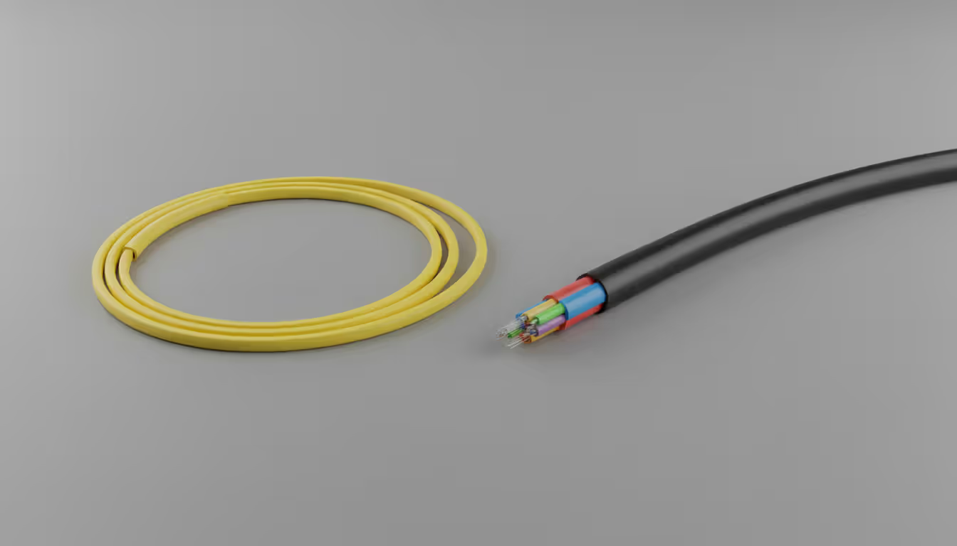
Tight-buffered cable construction applies a 900-micron plastic coating directly over the 250-micron coated fiber. This design provides crush resistance and simplifies direct termination with connectors, making it the standard choice for indoor installations. The buffer layer protects fibers during installation through conduit and allows technicians to strip and cleave fibers without exposing bare glass to handling damage.
Loose-tube designs suspend fibers within gel-filled or dry tubes inside the cable jacket. This construction isolates fibers from external stresses—temperature fluctuations, cable tension, and moisture. Outdoor and underground installations almost exclusively use loose-tube cables because the fibers can move independently within the tube as the cable expands and contracts. A 500-meter outdoor run might experience several feet of cable length change between summer and winter; loose-tube construction prevents this from stressing the glass fibers.
Armored cables add a corrugated steel or aluminum layer beneath the outer jacket. This armor protects against rodent damage, crush forces, and accidental cuts during nearby excavation work. Direct-burial installations in areas with active gopher or rat populations justify the added cost—a single rodent bite through unarmored cable can take down an entire site. Armored cable also suits industrial environments where forklifts, pallet jacks, or heavy equipment might roll over exposed cable runs.
When selecting cable type, match construction to installation environment and termination requirements. Indoor riser-rated tight-buffered duplex cable works for vertical runs between floors in an office building. Outdoor loose-tube cables with flooding compound handle buried conduit runs between buildings. Armored loose-tube cable protects aerial spans where ice loading or wind might stress the cable. Trying to direct-terminate loose-tube fiber without breakout kits leads to frustration and failed connections.
Indoor vs Outdoor Single Mode Fiber
Indoor cables prioritize flame resistance and low smoke generation. Plenum-rated cables (OFNP) use fluoropolymer jackets that meet strict fire safety codes for installation in air-handling spaces. Riser-rated cables (OFNR) provide adequate fire resistance for vertical shafts. These cables typically use tight-buffered construction with lower fiber counts—2 to 24 fibers—matching typical floor-to-floor or equipment-to-equipment connections.
Outdoor cables emphasize environmental protection. Polyethylene jackets resist UV degradation and moisture penetration. Flooding compounds or water-blocking tapes prevent water migration if the jacket gets compromised. Loose-tube construction with high fiber counts—up to 288 fibers in a single cable—reduces the per-fiber installation cost for campus backbones or metropolitan networks. Temperature ratings from -40°C to +70°C ensure operation through extreme weather.
The transition between indoor and outdoor cables requires planning. Running outdoor cable inside buildings often violates fire codes because polyethylene jackets produce toxic smoke. Solutions include terminating outdoor cables at building entry points inside weatherproof enclosures, then transitioning to indoor-rated cable, or using special transition cables with dual jackets meeting both outdoor durability and indoor fire safety requirements.
Author: Caleb Merrick;
Source: clatsopcountygensoc.com
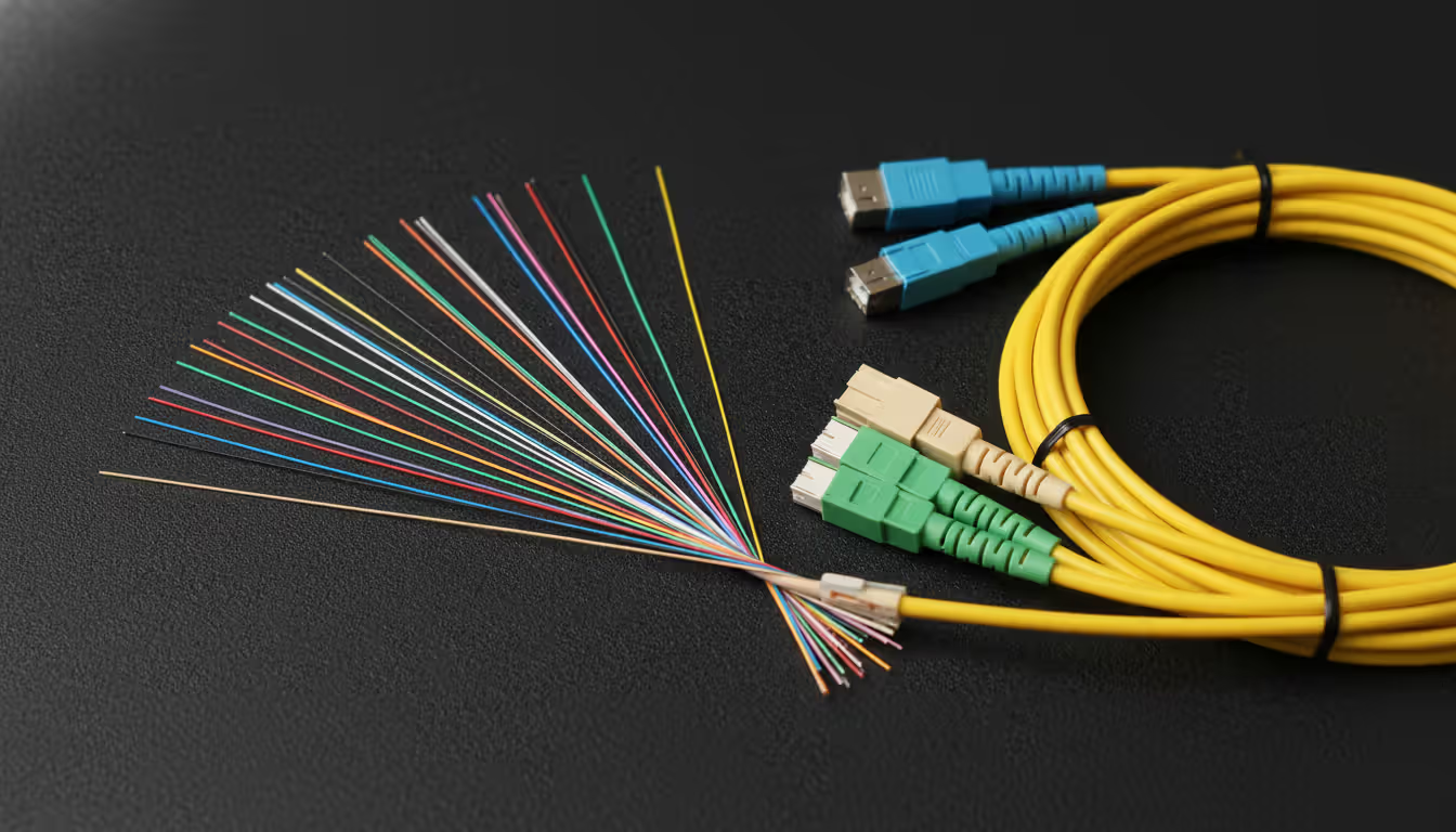
Single Mode Fiber Connector Types and Applications
LC (Lucent Connector) dominates modern installations through its small form factor and reliable performance. The 1.25mm ferrule—half the size of SC connectors—enables high port density on switches and patch panels. LC duplex connectors use a side-by-side configuration with a single latch mechanism, simplifying cable management in dense data center environments. Typical insertion loss runs 0.15-0.25 dB with return loss exceeding 50 dB for ultra-polished (UPC) versions.
SC (Subscriber Connector) connectors use a 2.5mm ferrule with push-pull coupling. While bulkier than LC, SC connectors remain common in telecommunications equipment and older installations. The square form factor prevents rotation during insertion, maintaining proper polarity. Many fiber distribution panels and wall outlets still specify SC because the larger connector body proves more durable in environments where non-technical staff might handle cables.
ST (Straight Tip) connectors feature a bayonet coupling mechanism with a 2.5mm ferrule. Once ubiquitous in enterprise networks, ST has largely been superseded by LC and SC in new installations. However, millions of ST connections remain in service, particularly in industrial control systems and building automation networks installed before 2015. Replacing functioning ST infrastructure solely for standardization rarely justifies the cost and downtime.
FC/PC (Ferrule Connector/Physical Contact) connectors use a threaded coupling nut and 2.5mm ferrule. The screw-on connection provides excellent vibration resistance, making FC connectors the choice for test equipment, fiber optic sensors, and high-vibration industrial applications. The threaded coupling takes longer to mate and demate than push-pull or latch designs, reducing FC's appeal for general networking.
Author: Caleb Merrick;
Source: clatsopcountygensoc.com
APC (Angled Physical Contact) connectors incorporate an 8-degree angle on the ferrule end face. This angle directs reflected light into the cladding rather than back toward the source, achieving return loss better than 60 dB. APC connectors—identifiable by green boots—are mandatory for GPON, RF-over-fiber, and other applications sensitive to back-reflection. Never mate APC to UPC connectors; the angle mismatch causes severe insertion loss and potential fiber damage.
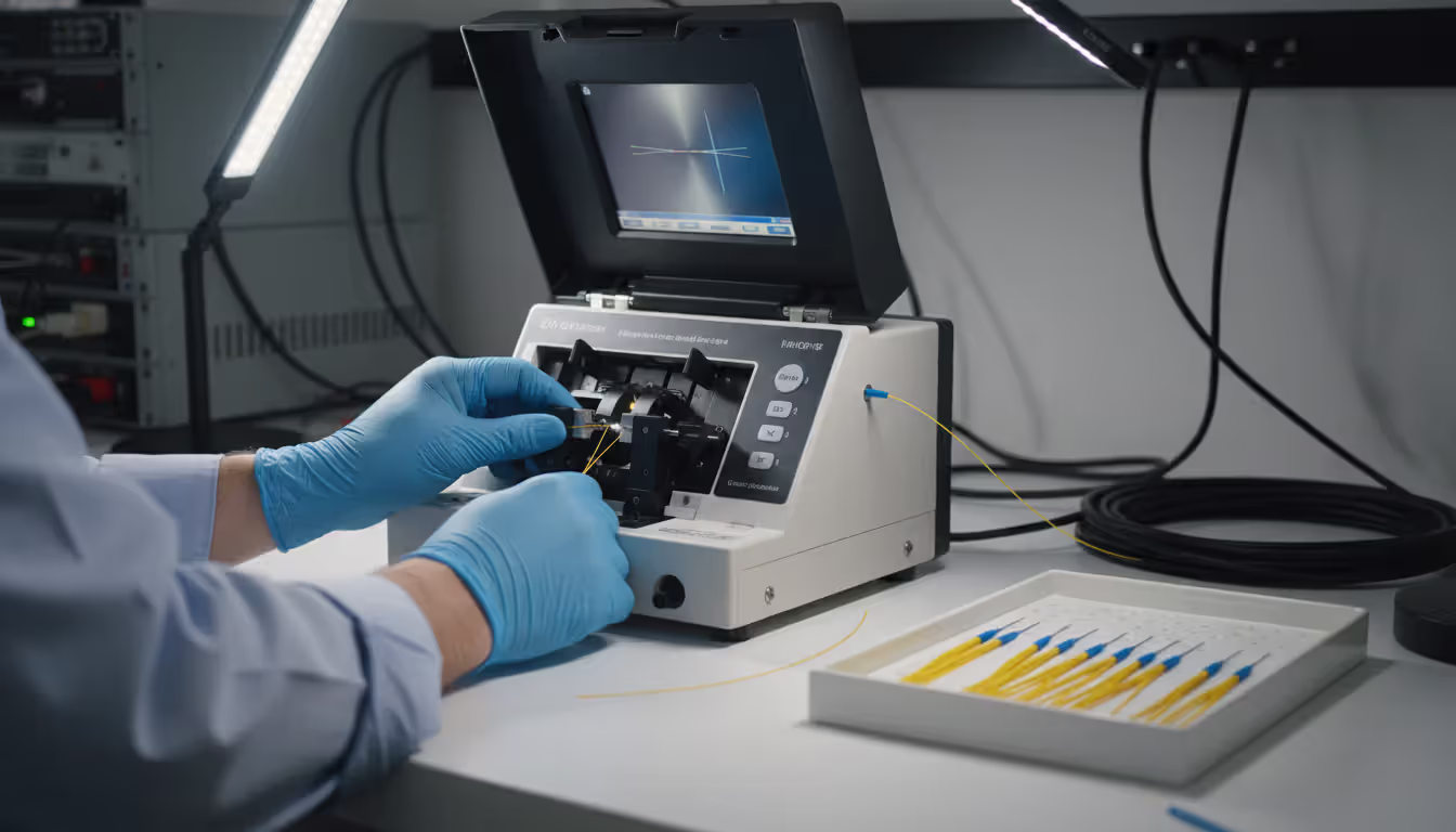
Compatibility considerations extend beyond mechanical fit. Ferrule end-face geometry significantly impacts performance. UPC (Ultra Physical Contact) connectors use a slightly curved polish that ensures fiber cores touch when mated. APC connectors require the 8-degree angle. Mixing polish types or using dirty connectors causes insertion loss spikes and intermittent connectivity. A proper connector inspection microscope should be standard equipment for any team terminating or troubleshooting fiber connections.
Installation and termination methods vary by connector type. LC and SC connectors work with both fusion splicing (using pre-terminated pigtails) and field-termination using epoxy or mechanical splice techniques. Fusion splicing produces the lowest loss—typically 0.05 dB per splice—but requires a fusion splicer costing $3,000-$15,000. Mechanical splice connectors cost $5-$15 each and require only a cleaver, but insertion loss runs 0.3-0.5 dB. For small projects with limited fiber terminations, mechanical splicing makes economic sense. High-fiber-count installations justify fusion splicing through lower per-connection costs and better long-term reliability.
| Connector Type | Typical Use Case | Insertion Loss | Return Loss | Best Applications |
| LC | Data centers, modern enterprise | 0.15-0.25 dB | >50 dB (UPC) | High-density switch connections, SFP+ modules |
| SC | Telecom equipment, premises | 0.25-0.35 dB | >50 dB (UPC) | Fiber distribution panels, wall outlets |
| ST | Legacy networks, industrial | 0.30-0.40 dB | >45 dB | Building automation, existing installations |
| FC/PC | Test equipment, sensors | 0.20-0.30 dB | >45 dB | Vibration-prone environments, instrumentation |
| FC/APC | GPON, RF-over-fiber | 0.20-0.30 dB | >60 dB | Applications requiring minimal back-reflection |
Single Mode Fiber Color Coding Standards
TIA-598 establishes yellow as the standard jacket color for single mode fiber cables. This immediately distinguishes single mode from multimode fiber, which uses orange (OM1/OM2), aqua (OM3/OM4), or lime green (OM5) jackets. The color coding prevents technicians from accidentally cross-connecting incompatible fiber types—connecting a 10GBASE-SR multimode transceiver to single mode fiber produces no link, while connecting a 10GBASE-LR single mode transceiver to multimode fiber might work at short distances but fails unpredictably as distance increases.
Connector boot colors provide additional identification. Blue boots indicate UPC (Ultra Physical Contact) polish on single mode connectors, while green boots designate APC (Angled Physical Contact) connectors. This color scheme prevents the catastrophic error of mating UPC to APC connectors, which damages fiber end faces and requires re-termination. Some manufacturers use beige or white boots for UPC single mode connectors on legacy equipment, creating potential confusion—always verify polish type before making connections.
Individual fibers within multi-fiber cables follow a twelve-color sequence: blue, orange, green, brown, slate, white, red, black, yellow, violet, rose, and aqua. This pattern repeats for cables exceeding twelve fibers, with binder groups using the same color sequence to organize fiber bundles. Proper documentation of fiber assignments during installation prevents troubleshooting nightmares later. A simple spreadsheet mapping fiber colors to patch panel positions and destination equipment saves hours when tracking down connectivity issues.
The color coding differences from multimode fiber extend beyond jacket color. Multimode connectors typically use beige or black boots regardless of connector type, since multimode fiber doesn't use APC polish. This means you can't rely solely on boot color to identify fiber type—always check the cable jacket color or use a fiber identifier tool when working with unmarked patch cords.
Violations of color standards occur frequently with custom-length patch cords ordered from low-cost suppliers. A yellow jacket with orange boots might indicate single mode fiber with multimode connectors, creating a non-functional connection. Specifying connectors and cable type explicitly when ordering custom cords prevents these mismatches. For critical infrastructure, buying pre-made cords from reputable manufacturers ensures consistent quality and proper color coding.
Choosing the Right Single Mode Fiber for Your Project
Distance requirements drive the initial fiber selection decision. Spans under 2 kilometers between buildings on a campus work fine with OS2 fiber and standard LC connectors using 10GBASE-LR or 100GBASE-LR4 optics. Extending to 10 kilometers might require the same fiber but needs attention to splice and connector counts—each connection point adds 0.3-0.5 dB loss, and you need to stay within the transceiver's power budget. Beyond 10 kilometers, consider extended-reach optics or DWDM systems that amplify signals.
Environment considerations determine cable construction. Indoor horizontal runs in office spaces use plenum-rated tight-buffered duplex cable. Vertical riser shafts between floors need riser-rated cable unless they're part of the air-handling system, which requires plenum rating. Outdoor aerial runs between poles require cables with strength members rated for the span length and expected ice/wind loading. Underground conduit installations use loose-tube cables with water-blocking. Direct burial applications demand armored loose-tube cables with rodent protection.
Budget versus performance trade-offs appear at multiple decision points. Mechanical splice connectors cost less than fusion splicing for small projects, but the higher insertion loss reduces maximum span length. Pre-terminated cable assemblies with factory-installed connectors cost more than bulk cable with field termination, but eliminate installation errors and reduce labor costs. Armored cable runs 30-50% more than unarmored, but prevents costly repairs from rodent damage. Running extra "dark" fibers during initial installation costs little compared to pulling additional cables later when capacity needs grow.
Common mistakes include undersizing fiber counts for future growth. Installing 12-fiber cable when you need 4 fibers today provides expansion capacity at minimal additional cost—the cable price difference between 12 and 24 fibers might be 15%, but pulling new cable later costs thousands in labor and downtime. Another frequent error involves mixing connector types unnecessarily. Standardizing on LC connectors throughout a facility simplifies spare parts inventory and reduces technician training requirements.
Ignoring proper documentation ranks among the most expensive mistakes. A fiber run between buildings might traverse multiple splice closures, intermediate panels, and cross-connects. Without accurate records showing which physical fiber connects which endpoints, troubleshooting becomes an exercise in trial and error. Creating as-built documentation during installation—including fiber colors, splice closure locations, and test results—pays dividends for the life of the infrastructure.
Single mode fiber adoption in enterprise networks accelerated dramatically after 2020 as 100G and 400G switching became cost-effective.Organizations that deployed single mode for their data center spine and inter-building links gained a clear upgrade path to higher speeds without replacing infrastructure. The slightly higher initial cost compared to multimode proves negligible when you avoid forklift upgrades every five years
— Michael Chen
Frequently Asked Questions
Selecting appropriate single mode fiber requires balancing technical specifications against installation environment and budget constraints. The 9/125 micron core size and OS2 performance classification provide the foundation for reliable long-distance data transmission, while proper attention to connector types, cable construction, and color coding prevents costly installation errors. Understanding the trade-offs between tight-buffered and loose-tube designs, armored versus unarmored construction, and fusion versus mechanical splicing allows network designers to optimize infrastructure for both current requirements and future expansion. As data rates continue climbing toward 800G and beyond, the transmission distance and bandwidth advantages of single mode fiber become increasingly valuable, justifying its position as the default choice for inter-building links, data center spines, and metropolitan networks.
Related Stories

Read more

Read more


The content on this website is provided for general informational and educational purposes related to cloud computing, network infrastructure, and IT solutions. It is not intended to constitute professional technical, engineering, or consulting advice.
All information, tools, and explanations presented on this website are for general reference only. Network environments, system configurations, and business requirements may vary, and results may differ depending on specific use cases and infrastructure.
This website is not responsible for any errors or omissions, or for actions taken based on the information, tools, or technical recommendations presented.